Experimental Validation of Aibuild FETS
GPU-accelerated thermomechanical simulation of a WAAM weave wall, validated against independent IR thermography and 3D scan data
This validation was performed as part of COMPADDITIVE, a research project funded by an Innovate UK grant, in collaboration with Additure, AMRC and Turkish Aerospace Industries.
Executive summary
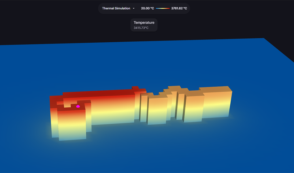
Aibuild FETS is a GPU-accelerated, fully transient thermomechanical finite-element solver for large-scale additive manufacturing. This study validates FETS end to end — thermal solution and final distortion —against experimental data produced independently by Additure under the COMPADDITIVE project: a 15-layer weave-deposited WAAM wall on a clamped mild steel base plate, instrumented with per-layer infrared thermography and high-resolution 3D scans before and after printing.
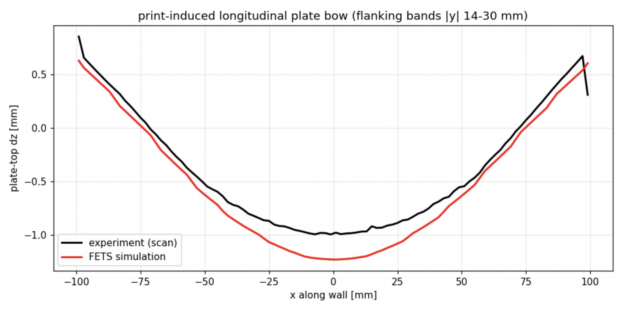
- Plate longitudinal bow (edge-to-centre)
- Experiment 1.85 mm · FETS 1.86 mm · Agreement 101%
- Plate bow profile RMSE
- FETS 0.15 mm
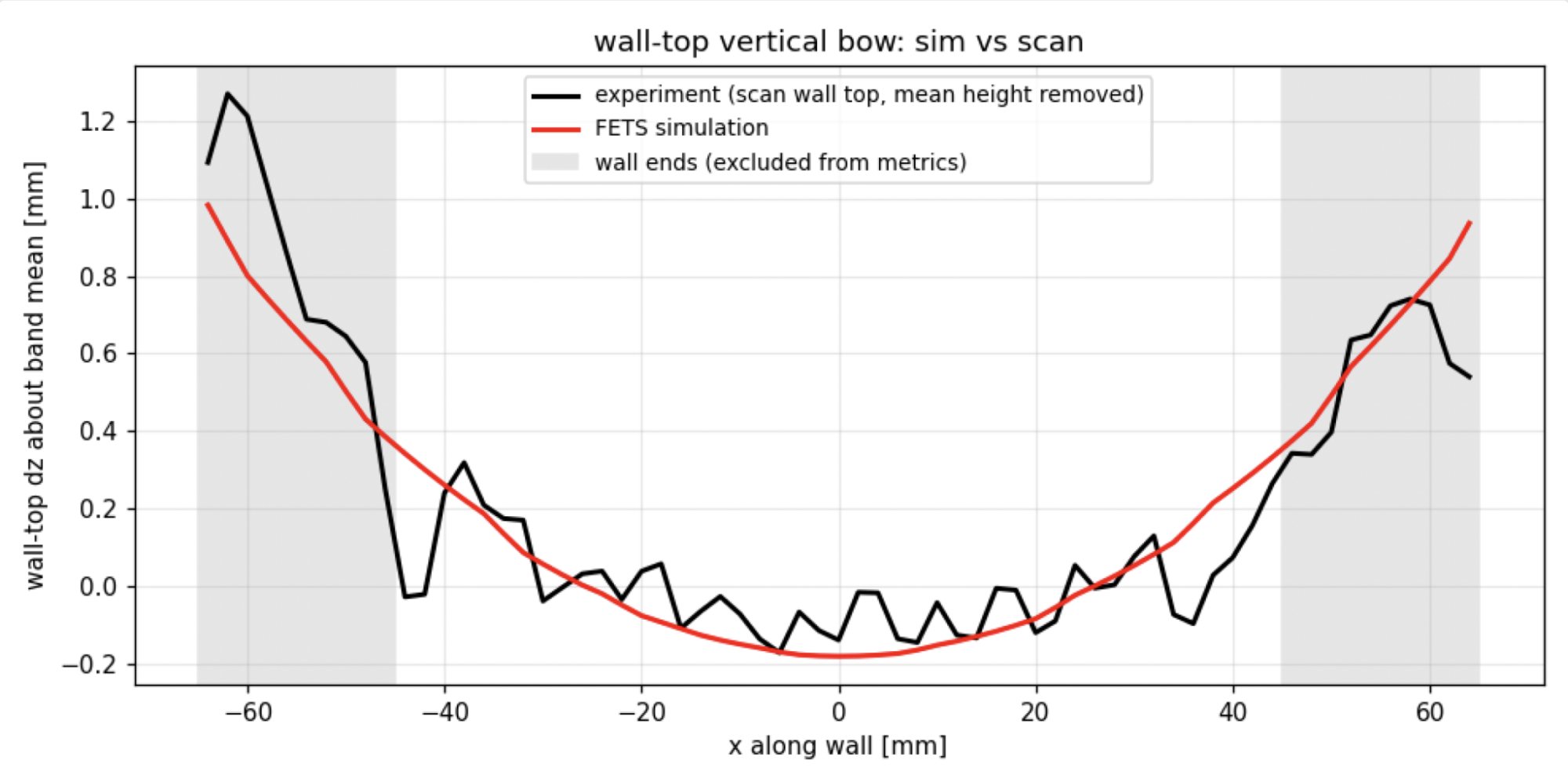
- Wall-top vertical bow (centre-to-band-edge)
- Experiment 0.49 mm · FETS 0.52 mm · Agreement 107%
- Full-field distortion RMS error (plate / wall faces / wall top)
- FETS 0.12 / 0.10 / 0.13 mm
- Wake-cooling temperature error, MAE (700–1450 °C band, 15 layers)
- FETS 104 °C (≈7% of range) · bias +11 °C
The full simulation — a moving heat source following the actual weave toolpath through a 30-minute print, plus cool-down to ambient and clamp release, with J2 plasticity and temperature-dependent properties on an 80,460-element mesh — ran in 6.2 minutes of wall-clock time on a single laptop GPU (NVIDIA RTX 5090 Laptop) at the solver’s high-accuracy settings.
The experiment
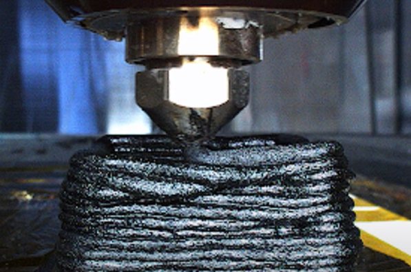
Additure printed a single weaving wall by wire-arc additive manufacturing (WAAM / arc DED) and captured both the thermal history and the final geometry — an ideal test case, because it exercises the two halves of a thermomechanical solver independently.
- Part
- Wall, 150 × 20 × 30 mm (L × W × H), 15 layers
- Deposition strategy
- Meander / weave, 3.5 mm track distance, 2 mm layer height
- Wire
- Union K56 (EN ISO 14341-A G 46 4 M21 3Si1, ER70S-6 class)
- Travel / wire feed
- 1500 mm/min travel, 9.5 m/min wire feed
- Arc power
- 4.27 kW (230 A, 16.3 V)
- Layer cycle
- Fixed 120 s (≈33.5 s deposition + 86.5 s dwell)
- Base plate
- Mild steel, 200 × 200 × 10 mm
- Clamping
- Two edge clamp bars along opposite plate edges, released after cool-down
Instrumentation
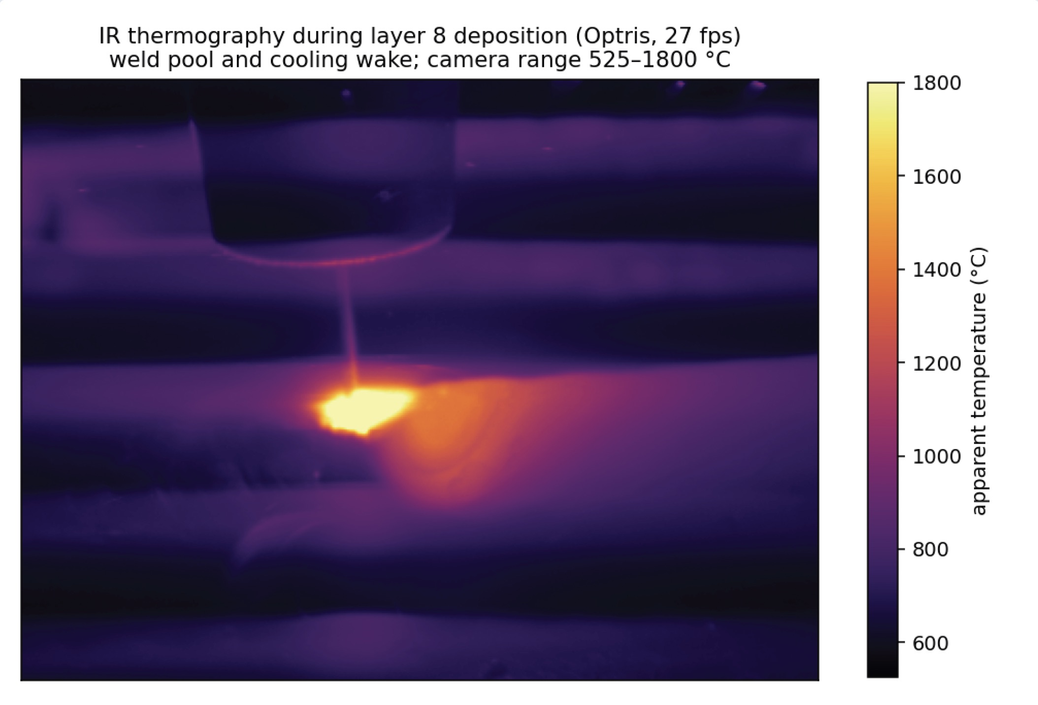
- IR thermography — an Optris radiometric camera recorded every layer at 27 fps (calibrated measurement band 525–1800 °C), viewing the wall side face. This gives per-layer wake-cooling curves: the temperature decay at a fixed point after the torch passes — a demanding transient signal that couples heat input, conduction and surface losses.
- 3D scanning — dimensional scans of the plate before printing, of the clamped assembly after printing, isolates the print-induced distortion from any pre-existing plate non-flatness; the clamped scan additionally pins down the true clamp contact footprint used in the model.
Simulation setup
FETS solves the coupled problem the direct way — no inherent-strain shortcuts, no layer lumping:
- Transient thermal solve with a moving heat source. The heat input follows the actual G-code toolpath through every weave stroke of every layer, with adaptive time stepping (127,876 thermal steps over the print). Energy input rate mode: absorbed power = η × 4.27 kW.
- Nonlinear mechanics. J2 plasticity with isotropic hardening, temperature-dependent Young’s modulus, yield stress and thermal expansion, and annealing (plastic-strain reset) above the softening range. Full Newton-Raphson solves during the build, cool-down to ambient, then a clamp release solve for the free-state distortion.
- Model. Voxel hex mesh generated directly from the G-code: 96,315 nodes / 80,460 elements (289k mechanical DOF); 1.75 × 1.75 × 2 mm bead cells. Two materials: K56 weld metal for the wall, mild steel for the plate. Clamp constraints match the contact strips measured off the clamped scan (edge bars pressing ≈9 mm inboard along the two plate edges).
- Simulated physical time
- 30 min print + 75 min cool-down
- Wall-clock time
- 374 s (6.2 min)
- Hardware
- 1× NVIDIA RTX 5090 Laptop GPU
- Solver health
- 100% — all 128k+ thermal and all mechanical solves converged, no rollbacks
Step 1 — thermal validation and calibration
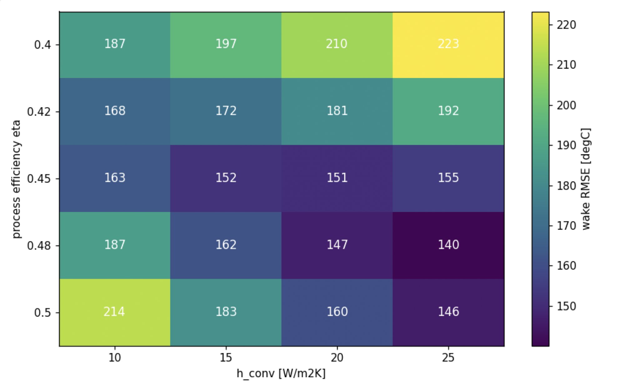
Two effective parameters were calibrated, exactly as in production use of the solver: the arc process efficiency η (fraction of arc power entering the part) and the effective surface heat-loss coefficient h (convection plus linearised radiation). Everything else — material data, toolpath, timing — is fixed by the process specification.
The calibration signal is the wake-cooling curve: at a fixed point on the wall side face, temperature vs time since the torch passed, extracted per layer from the IR recordings (median across anchor points along the wall, trusted between 700 and 1450 °C). A 5 × 4 sweep over (η, h) finds a clear error valley:
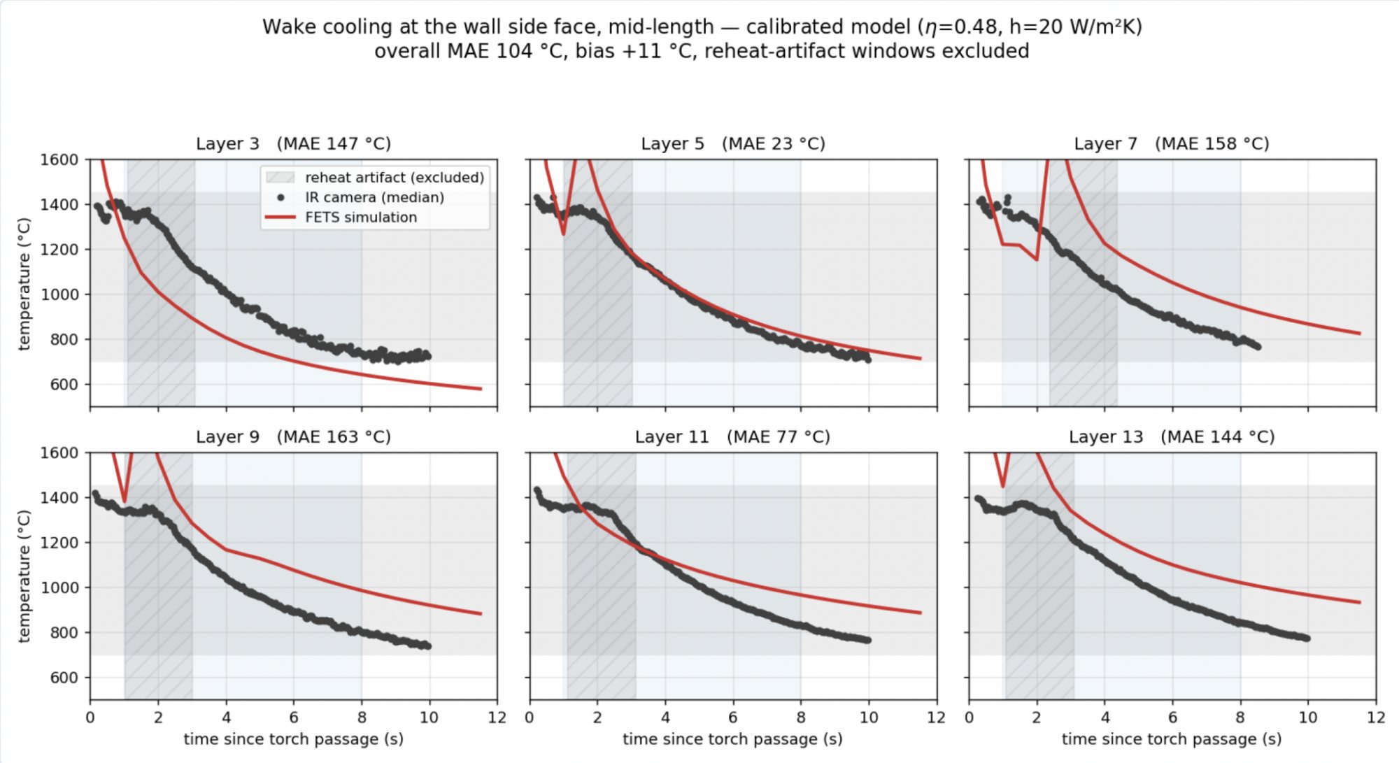
At the calibrated point the simulated cooling transients track the IR measurement across all 15 layers — including the layer-to-layer heat accumulation as the wall grows — with an overall mean absolute error of 104 °C and near-zero bias (+11 °C) over a signal spanning 700–1450 °C. That error is about 7% of the ~1430 °C range from ambient to the peak measured temperature. (Brief windows in which the simulation’s discrete element activation re-deposits bead next to the probe point are excluded from the score; see the appendix.)
Step 2 — distortion validation
This is the blind test: with the thermal side calibrated, the mechanical prediction has no free parameters. Material plasticity data comes from handbook values for the wire class, and the clamp constraints from the clamped-condition scan.
Methodology
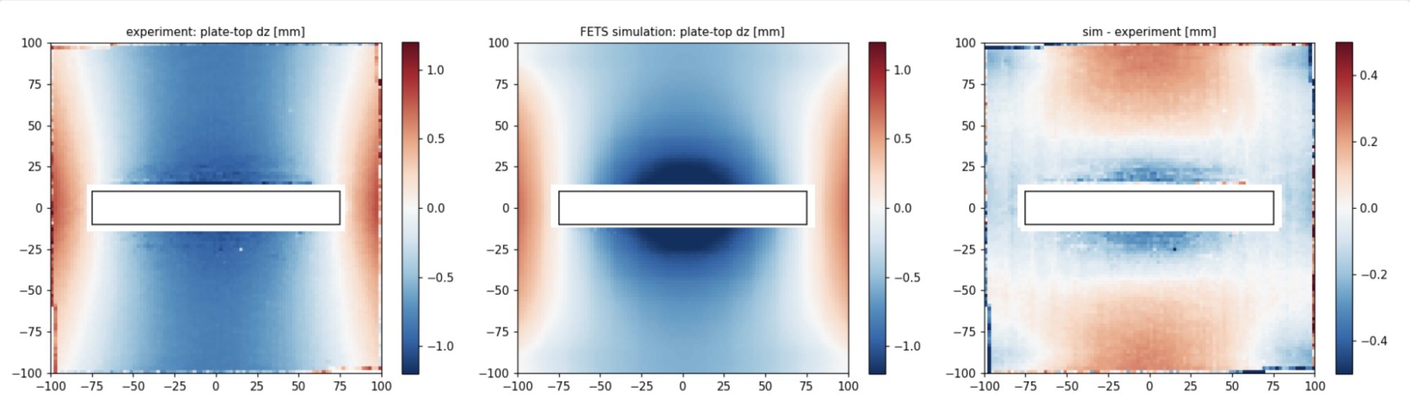
The final-part scan is registered to the nominal geometry (PCA + rigid ICP on the plate), and the registered before-print scan is subtracted so that only print-induced deviation remains. Two artefact classes are removed before comparison, both documented in the appendix: a small rigid registration tilt of the final scan (4 mrad, 83% planar in the difference map), and — on the wall itself — deposition-process geometry (bead ripple, a 1.7 mm torch-path placement offset, and the systematic ~5% under-height of as-deposited layers) that no thermomechanical solver models.
Base plate
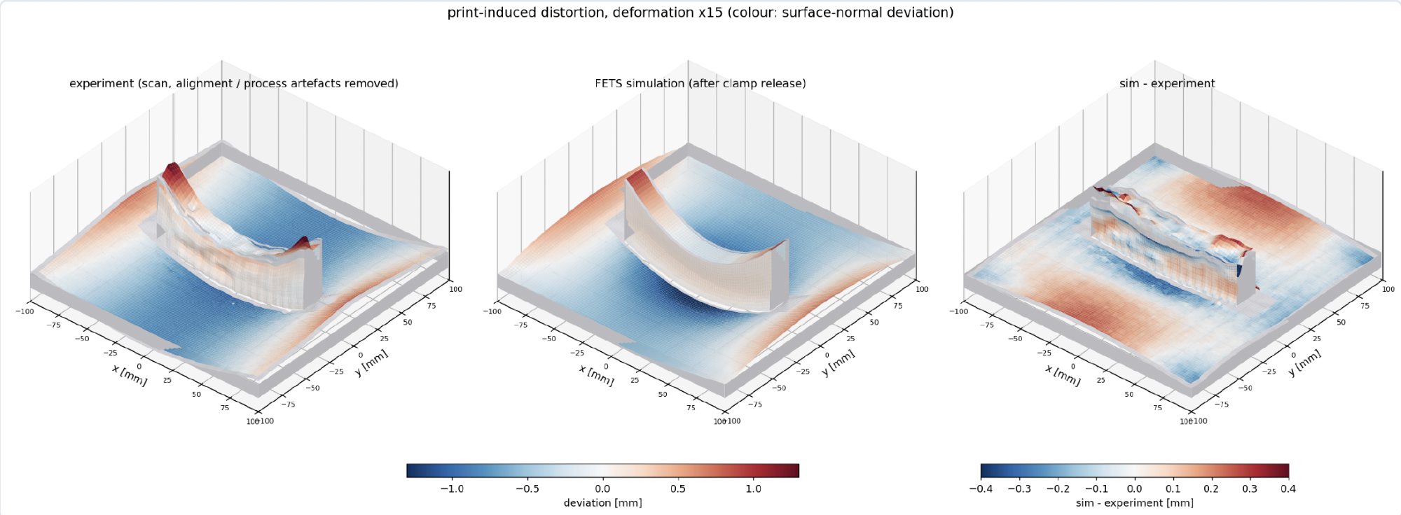
The plate develops the classic longitudinal saddle: edges lift, centre dips, ~1.9 mm edge-to-centre. FETS predicts both the shape and the magnitude:
Wall
Laterally, the wall’s as-deposited surface geometry (bead ripple RMS 0.43 mm) dominates over its thermal distortion (< ±0.1 mm predicted and measured) — an experimental finding in itself: for this geometry, lateral wall accuracy is a deposition-control problem, not a distortion problem.
Vertically, however, the wall top carries a clean mechanical signal: it follows the plate saddle upward at the ends. After removing the uniform under-height, the measured wall-top bow is +0.49 mm centre-to-band-edge vs +0.52 mm predicted (107%), RMSE 0.12 mm — at the bead-ripple noise floor:
Full field
Bringing it together, the sim-vs-experiment RMS over the entire visible surface of the part is ~0.1 mm everywhere: 0.12 mm on the plate top, 0.10 mm on the wall side faces, 0.13 mm on the wall top — roughly an order of magnitude smaller than the distortion signal being predicted.
Conclusions
- Accurate. With a standard two-parameter thermal calibration and no mechanical tuning at all, FETS predicted the dominant distortion mode of this WAAM build to within 1% (plate bow) and 7% (wall-top bow), with full-field residuals of ~0.1 mm RMS — at the noise floor of the scan-based measurement itself.
- Fast. The result came from a fully transient simulation — every weave stroke of every layer — in 6.2 minutes on a single laptop GPU. That turnaround makes distortion-compensated toolpaths, clamp-layout studies and process-parameter sweeps practical inside a CAM workflow, rather than overnight HPC jobs.
- Transferable. The agreement was achieved with the direct thermo-elasto-plastic formulation, not geometry-specific strain scaling: the same calibrated (η, h) pair is expected to transfer across parts printed with the same machine, wire and shielding conditions.
Appendix — methodology notes
IR temperature calibration. The Optris .ravi recordings store raw counts; the counts→temperature mapping (T = (counts − 1000)/10 °C, apparent temperature at emissivity 1.0) was verified frame-by-frame against the on-screen readouts of a synchronized PIX Connect screen recording (weld-pool motion cross-correlation 0.98). The camera’s calibrated band is 525–1800 °C; comparisons use 700–1450 °C to stay clear of the range edges.
Effective surface losses. FETS models surface heat loss with a convection boundary condition; the calibrated h = 20 W/m²K is an effective coefficient absorbing convection and radiation. Consistently, η = 0.48 is an effective absorbed-power fraction that also absorbs weld-pool losses (spatter, vaporisation) relative to nominal arc power.
Reheat-artifact exclusion. FETS activates deposited elements in batches (~1.2 s of bead per batch) at the adiabatic superheat temperature. When the adjacent weave stroke re-passes within a few millimetres of the probe point, this appears as a brief artificial spike in the simulated wake curve; the IR data shows the same physical event as only a 10–30 °C shoulder. The ~2 s windows following these batched activations, computed from the activation schedule, are excluded from the quoted error (including them gives MAE 116 °C; the equivalent RMSE figures are 128 °C excluded / 147 °C included).
Scan registration and tilt. Scans are registered by PCA followed by rigid ICP on plate regions only (no scaling). The before-print scan registers to 0.05 mrad; the final scan — a saddle-shaped plate fitted to a flat nominal with asymmetric occlusions — acquires a 4.0 mrad tilt about the wall axis, identified because the sim-experiment difference map is 83% planar. This single rigid tilt is removed from the experimental field; raw (uncorrected) agreement on plate bow is 89%.
Wall-face cleaning. For the full-field comparison, the wall scan is cleaned of deposition-process geometry: bodily placement offset (+1.7 mm) and in-plan yaw (−11 mrad) of the torch path relative to the plate, mean under-width and under-height of the deposited beads, and bead/weave ripple (6–10 mm smoothing). These are real and repeatable features of the deposition process, but they are geometry delivery errors, notdistortion, and no thermomechanical code predicts them.
Experimental data courtesy of Additure, produced under COMPADDITIVE — a research project funded by an Innovate UK grant, in collaboration with Additure, AMRC and Turkish Aerospace Industries. Simulation, calibration and analysis: Aibuild.